Air Conditioner Assembly Line Design Layout—Air Conditioner Assembly Line Design and Fabricate Factory
Description
We specialize in providing comprehensive solutions for Air Conditioners Assembly Lines/Production Lines.
Air Conditioner Assembly Lines/Production Lines are Suitable to Assemble/Produce Air Conditioners.(Welcome to contact us, we will suggest and design the suitable Assembly Lines/Production Lines for your Air conditioners.)

Air-Conditioner Assembly Line Design
This is the concrete output where plans are translated into drawings, typically using professional CAD software (e.g., AutoCAD, SolidWorks).
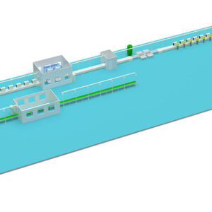
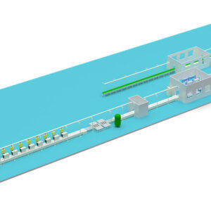
1. Factory Floor Plan Layout
Core Content: Precisely draw the exact locations of the production lines, equipment, workstations, warehouses, aisles, utility points (electricity, air, water), and fire safety equipment within the factory workshop.
Key Annotations:
Outline dimensions and positioning coordinates of all equipment.
Width of main aisles, logistics aisles, and pedestrian walkways.
Spacing between lines (ensuring enough space for maintenance and material handling).
Safety zones (e.g., performance test chambers need isolation for noise and heat).
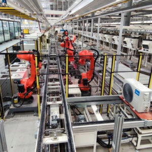
2. Production Line Detailed Design Drawings
Line Type Selection & Design: Select and design the conveyor system in detail, e.g.:
Slat Chain Conveyor: Good load-bearing capacity, suitable for heavy items (e.g., outdoor units).
Roller Conveyor: Suitable for connecting processes and making turns.
Belt Conveyor: Suitable for light loads or the packaging section.
Skate Wheel Conveyor: Non-powered, allows manual pushing, highly flexible.
Workstation Design: Detailed design of each station, including:
Workbench dimensions and structure.
Layout of tool holders and material bins (racks).
Location of utility drops (air, electricity, network).
Ergonomic facilities like lighting and fans.
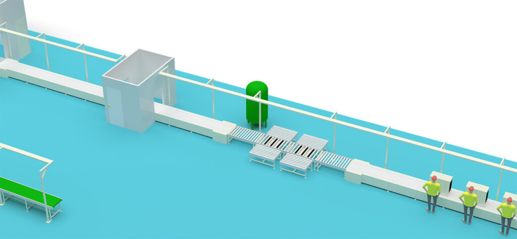
3. Material & Buffer Zone Design Drawings
Line-Side Storage Design: Plan how much material to store next to the line (typically 1-2 hours worth), and design the size and type of racks.
Supermarket Area: Plan a “supermarket” area near the line for standard parts.
Buffer Zones: Design necessary buffer zones before bottleneck processes or between stages, but minimize them to promote one-piece flow.
4. Utility Planning Drawings
Electrical Diagrams: Plan the routing, capacity, and distribution panel locations for power and lighting circuits.
Pneumatic Diagrams: Plan the routing of compressed air lines, drop points, and pressure requirements.
Water/Gas Diagrams: Especially for processes requiring cooling or cleaning, and drainage for performance test chambers.
Ventilation & HVAC: Ensure good ventilation in the workshop, particularly in painting, welding, and testing areas.